 Instrument Panel and Wiring
N247BR
Instrument Panel and Wiring
My Panel Construction - Part 2
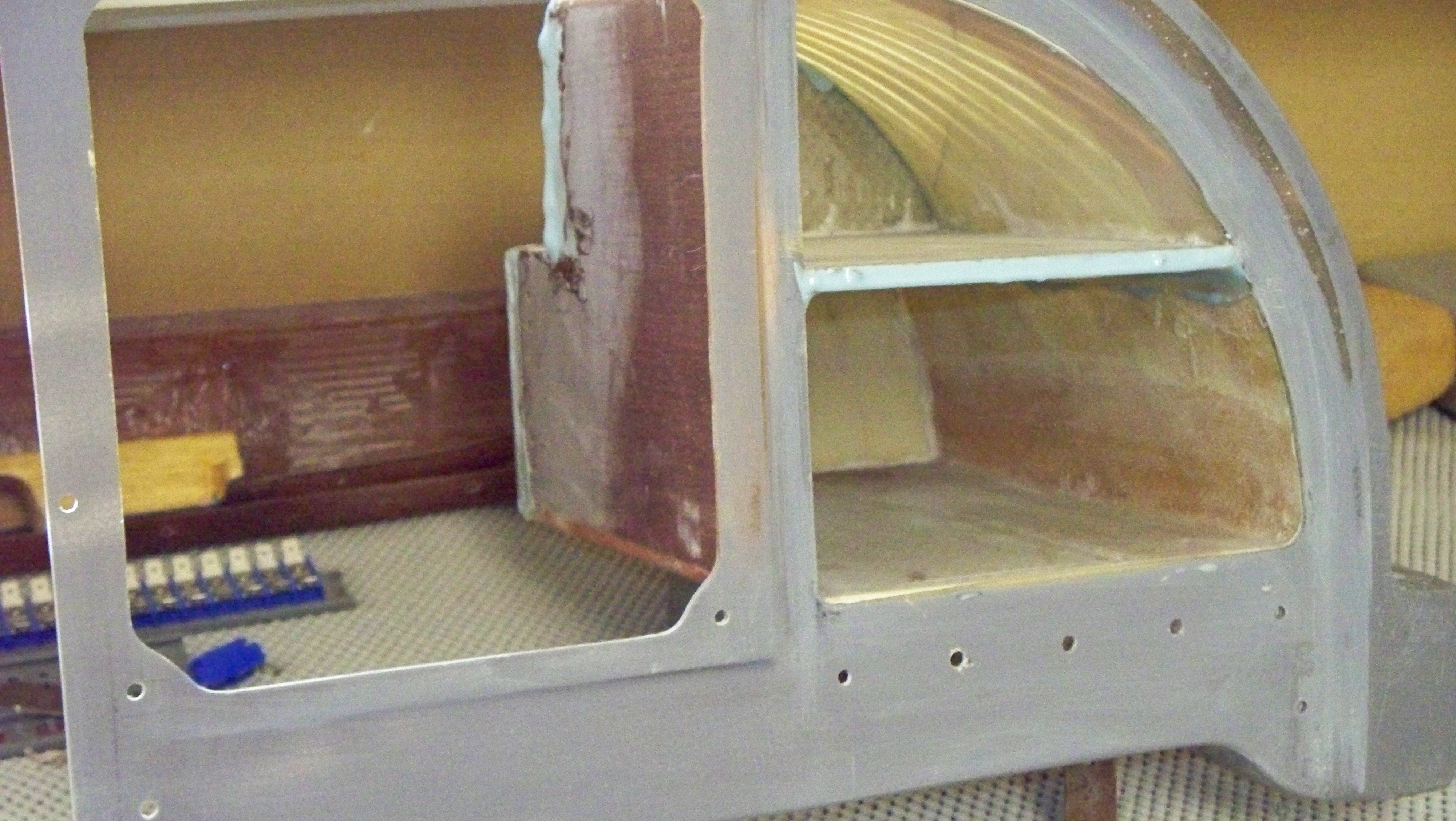 |
I finally closed out the glove box again after cutting off some of the back and top to make it fit properly. I added a shelf to give more usable space. I will add a small amount of glass around the edges to help hold everything together. My electrical connection panel will be mounted on the side which is 1/4 inch plywood. More pictures to follow. |
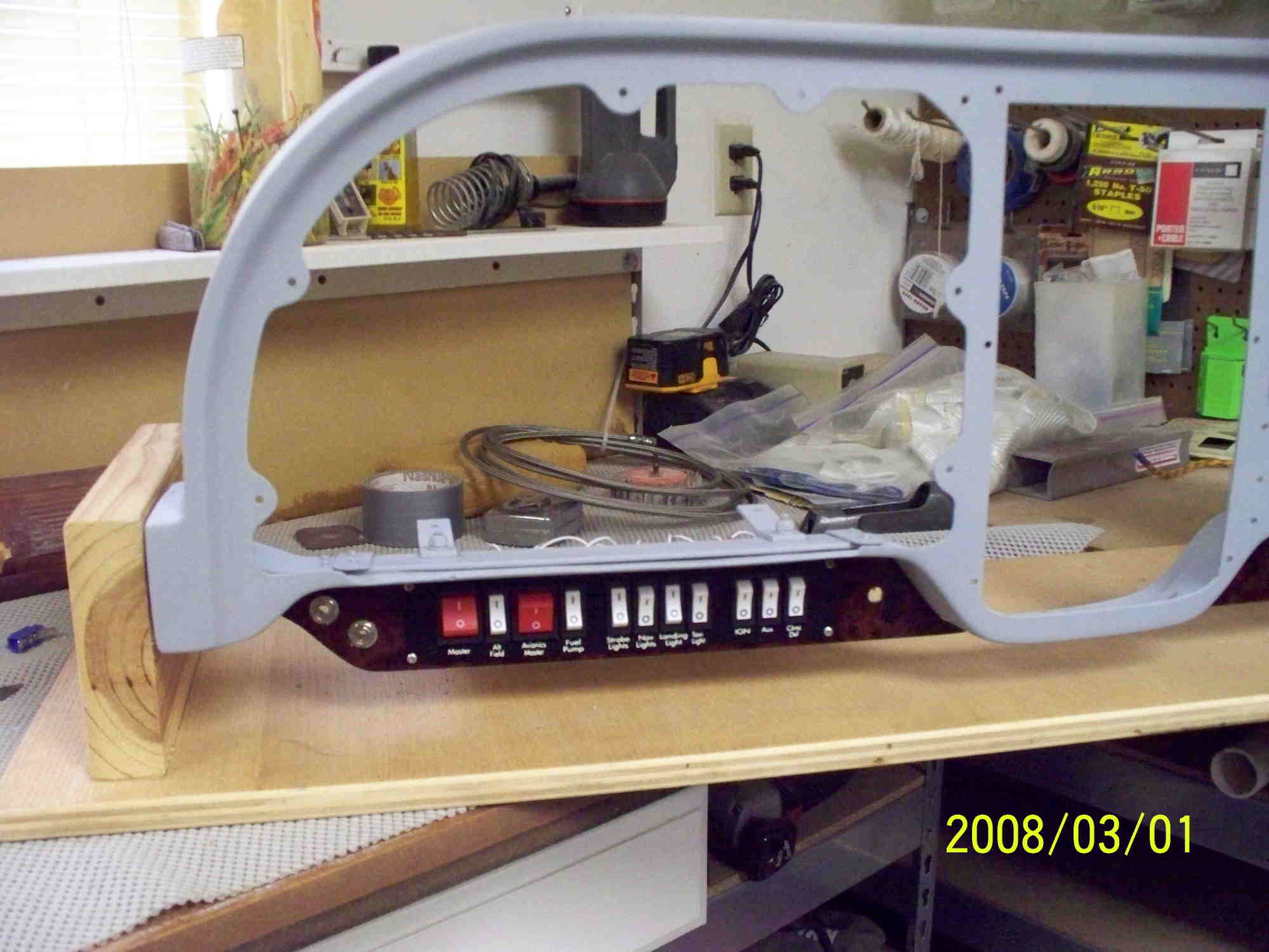 |
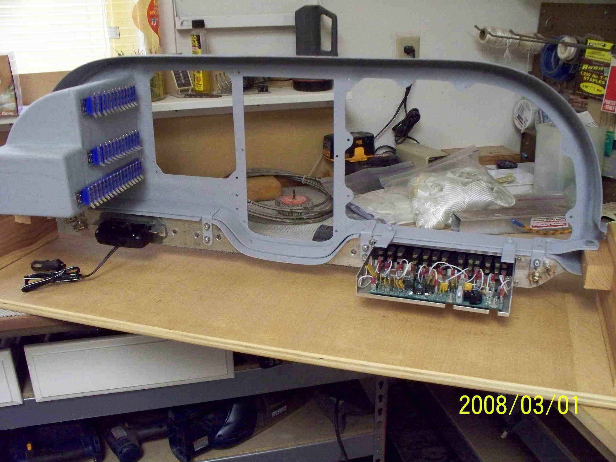
I have remounted the Instrument Panel on my working stand. Getting ready to start the wiring process. The Control Vision switch panel is in place. The headset connections are on the left side. The Emergency Brake control will be on the right side. |
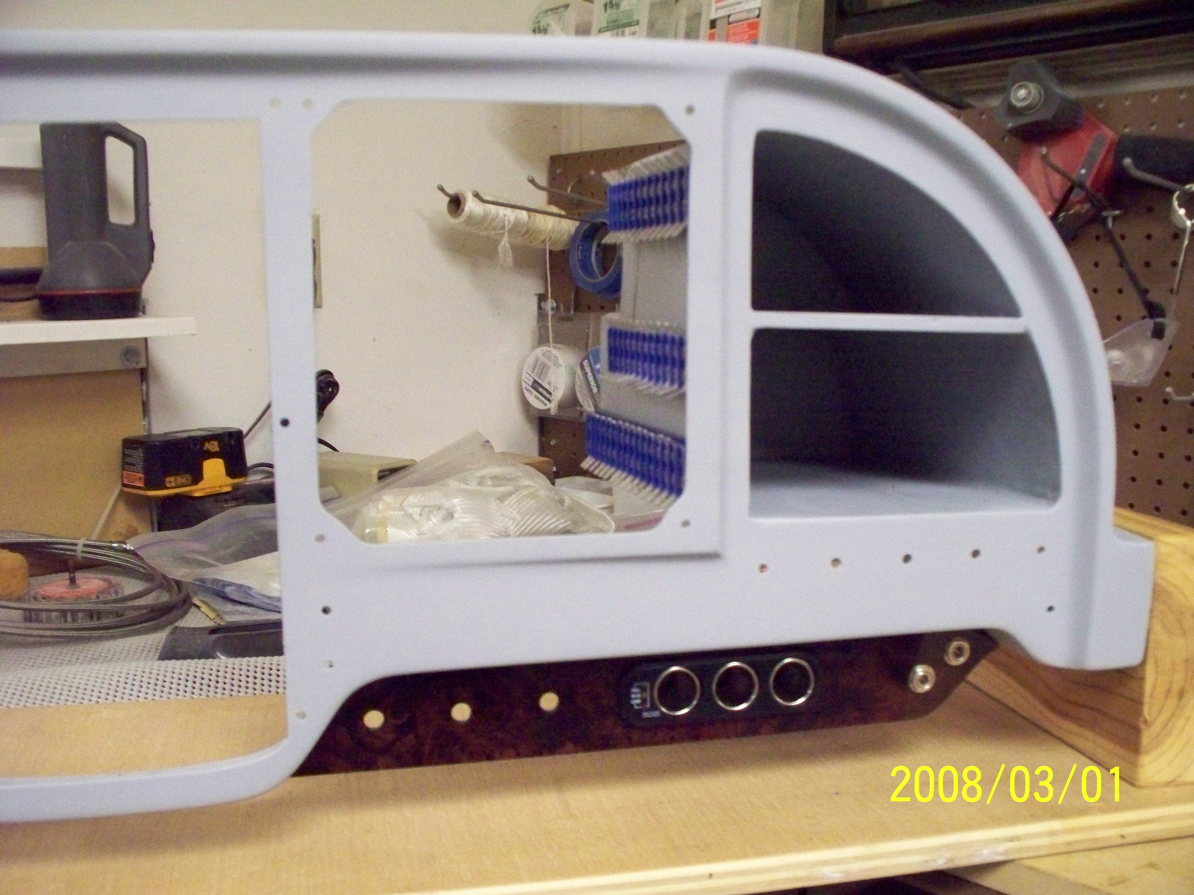 |
The panel has been primed front and back including the inside of the glove box. The contols under the panel include the headset connectors on the right side. The center has three power outlets that will be connected to a separte fuse box. The three holes on the left will contain the controls for the air controls. |
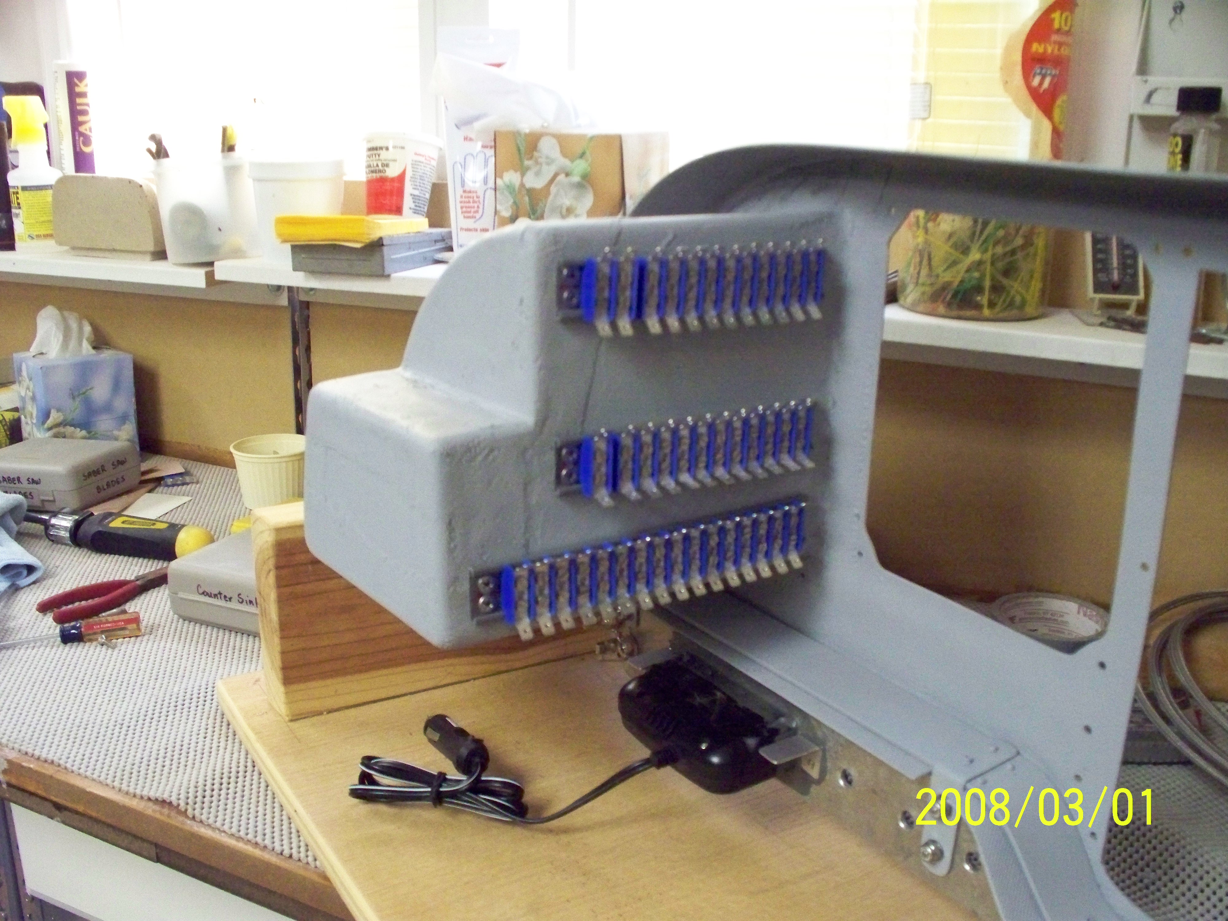 |
The Glove box was too long when I initially constructed it so I had to cut off the back end and part of the top. I added a shelf and rebuilt it as seen. The side of the glove box is used for the wiring panel. This will be the primary patch panel for all connections. The back of the triple power outlet can bee seen at the bottom. |
 |
The working mount allows full access from the front and
back. The wiring will run along the bottom of the panel to the
patch panel. Let the fun begin.
|