 Instrument Panel and Wiring
N247BR
Instrument Panel and Wiring
My Panel Construction - Part 1
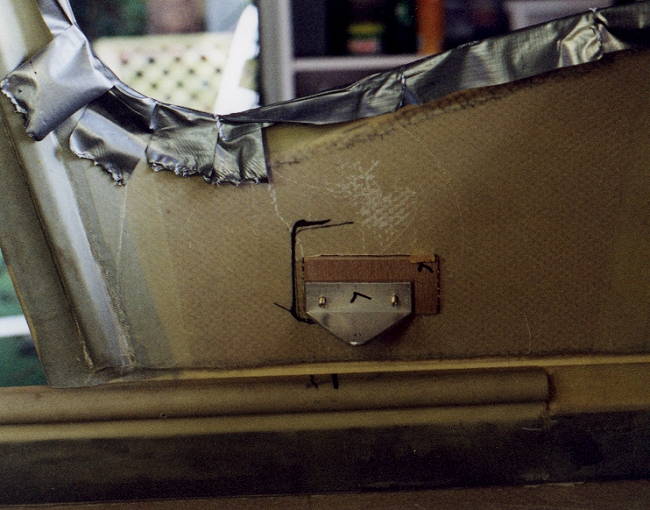 |
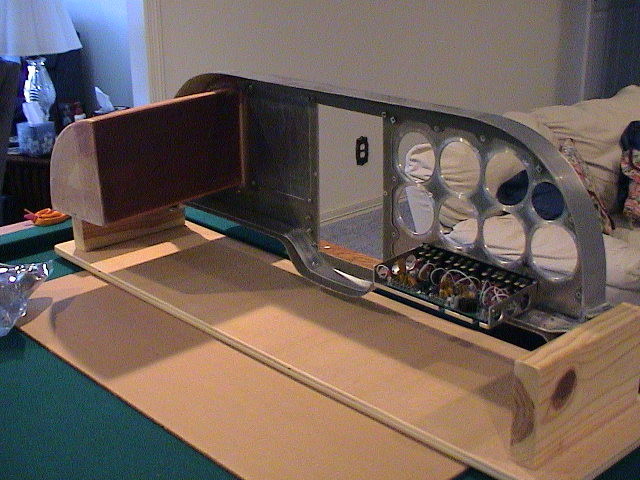
I decided to use a four point floating mounting system.
Two of the mount points will be on the sides of the fuselage as
shown. One will be on the bottom of the main panel attached to
the lower center console. The last point will be from the
avionics framework and attached to the center of the firewall.
All mounts will be shock mounts.
The duct tape is there for self protection, those edges are very, very sharp. |
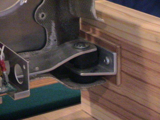 |
The mounts will use floating rubber shock mounts as shown
here. This system will allow the panel to move some and absorb
shocks without transfering them to the instruments.
A 1/8" aluminum bar extends across and is riveted to the bottom of the instrument panel. This carries the primary load and is attached at three points. The connection to the firewall will be attached to the top of the panel. |
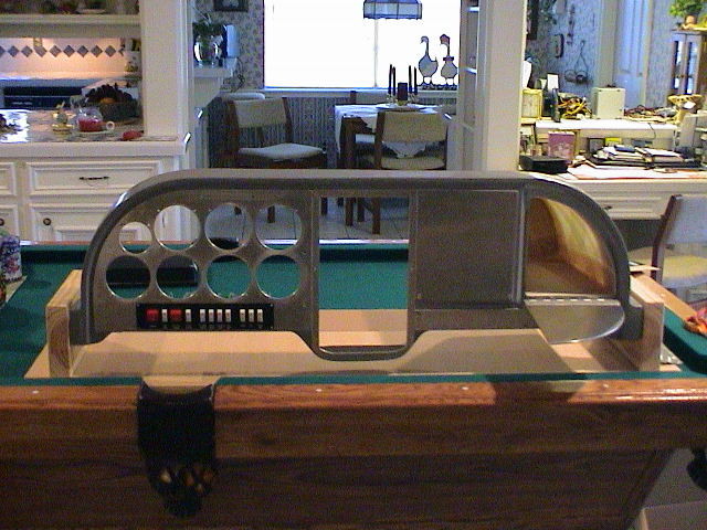 |
The initial layout included three removable panels for
instruments and avionics. The panels and glove box are all
fabricated from 1/8" aluminum sheet. The glove box is shown
open with the door hinged and folded down. The Control Vision
Fuse/Switch Panel is mounted below the primary instruments.
That was the plan but... |
 |
The primary instrument panel is removable and mounted by screws. This is the ONLY way to go as far as I am concerned. It makes for a very servicable panel. |
 |
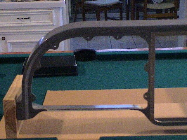
The rear view shows the extended glove box which will be
used for the wiring patch panel as well. The Control Vision
Switch panel can be seen too.
The panel is mounted on a working jig using the same mounts to be used for installation. Works like a champ and makes working on the panel very easy. The Glove Box proved to be too big and had to get cut down some. |
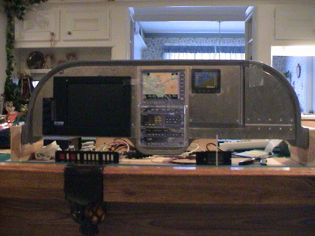 |
The new plan using the Blue Mountain EFIS One is shown
here. It is not complete yet but shows the EFIS One installation.
The FULL UPSAT Avionics Stack will probably not be used initially. The MFD functions are all included in the Blue Mountain EFIS and will probably be eliminated completely. |
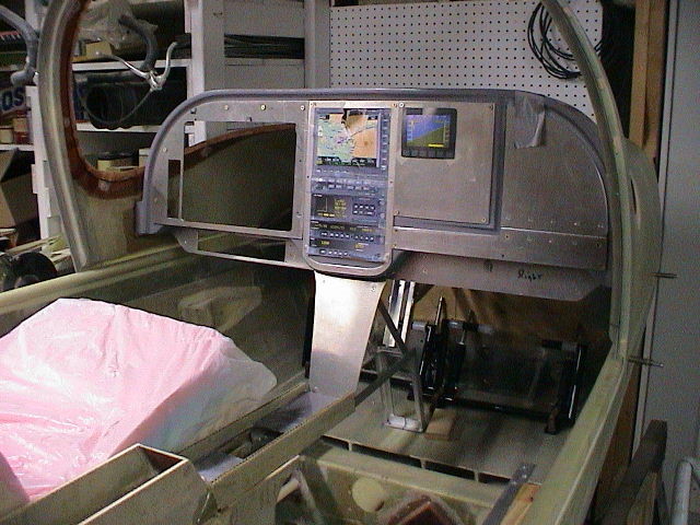 |
Fitting the instrument panel has proven to be a most interesting exercise. The Blue Mountain system takes up the entire area of the left side of the panel. I had already cut and fit the glove box which reduced my options on placement of the switches and other items. The best alternative seemed to be some extension to the panel. In order to work though the panel would need to be mounted a bit highter and further forward. The result is comfortable even with seats which are also somewhat higher than normal. |
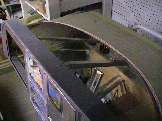 |
The panel is shock mounted on both sides, the bottom and the braces to the top are also shock mounted. The lower extension of the console / panel will be anchored to the floor and station 30. |