 |
| A nice CLEAN Firewall with nothing to clutter up the smooth clean surface. Now the fun begins. |
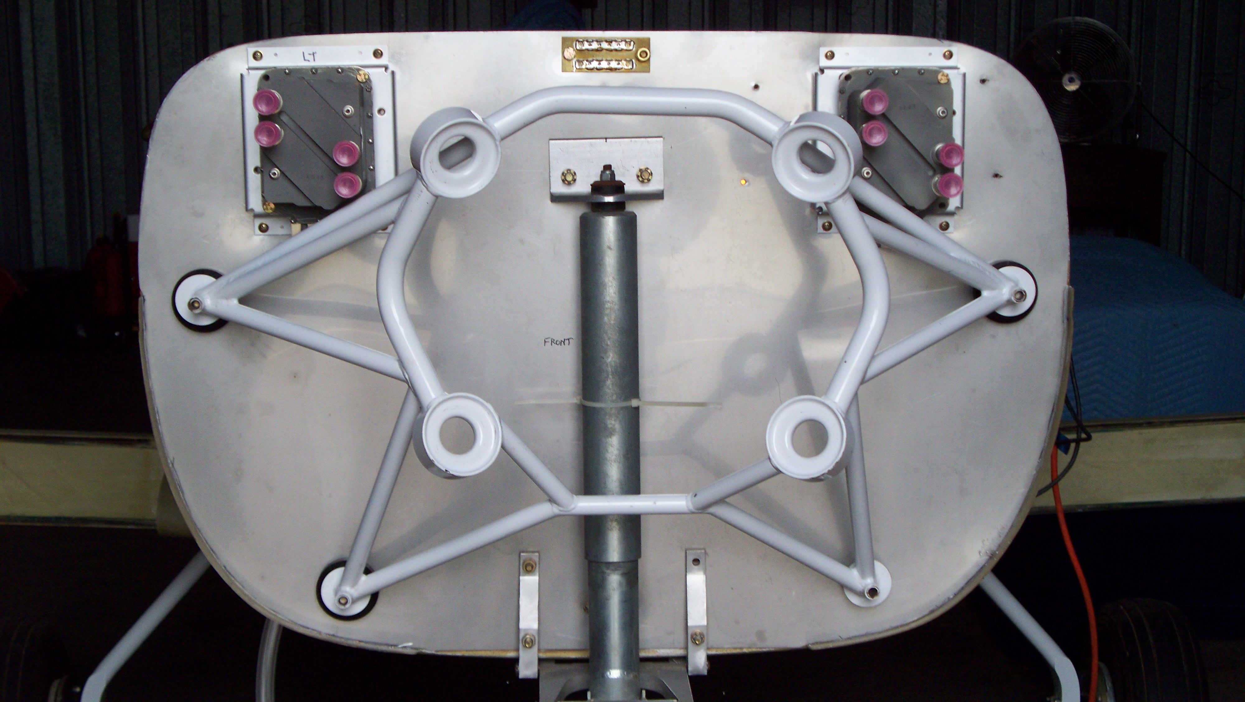 |
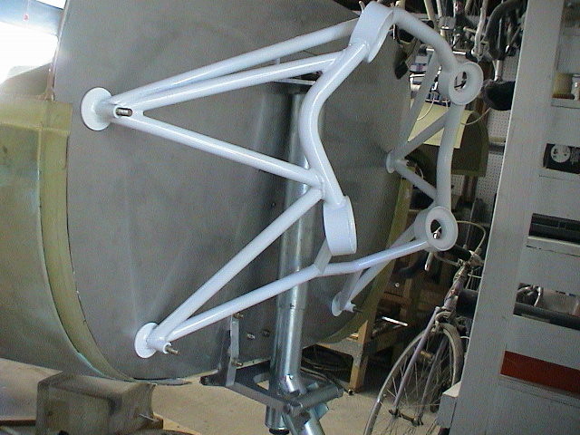
| First things first. The FADEC system electronic spark
controls are required to be placed within a certain area on either side of the center line. Problem number one, the engine mount covered almost every possible location for the sending units. The black rings around the pads on the engine mount are temporary 1" spacers needed to move the engine mount forward one inch. This not only opened up just enough space to mount the sending units, it will give needed space for the rear of the engine and accessories. |
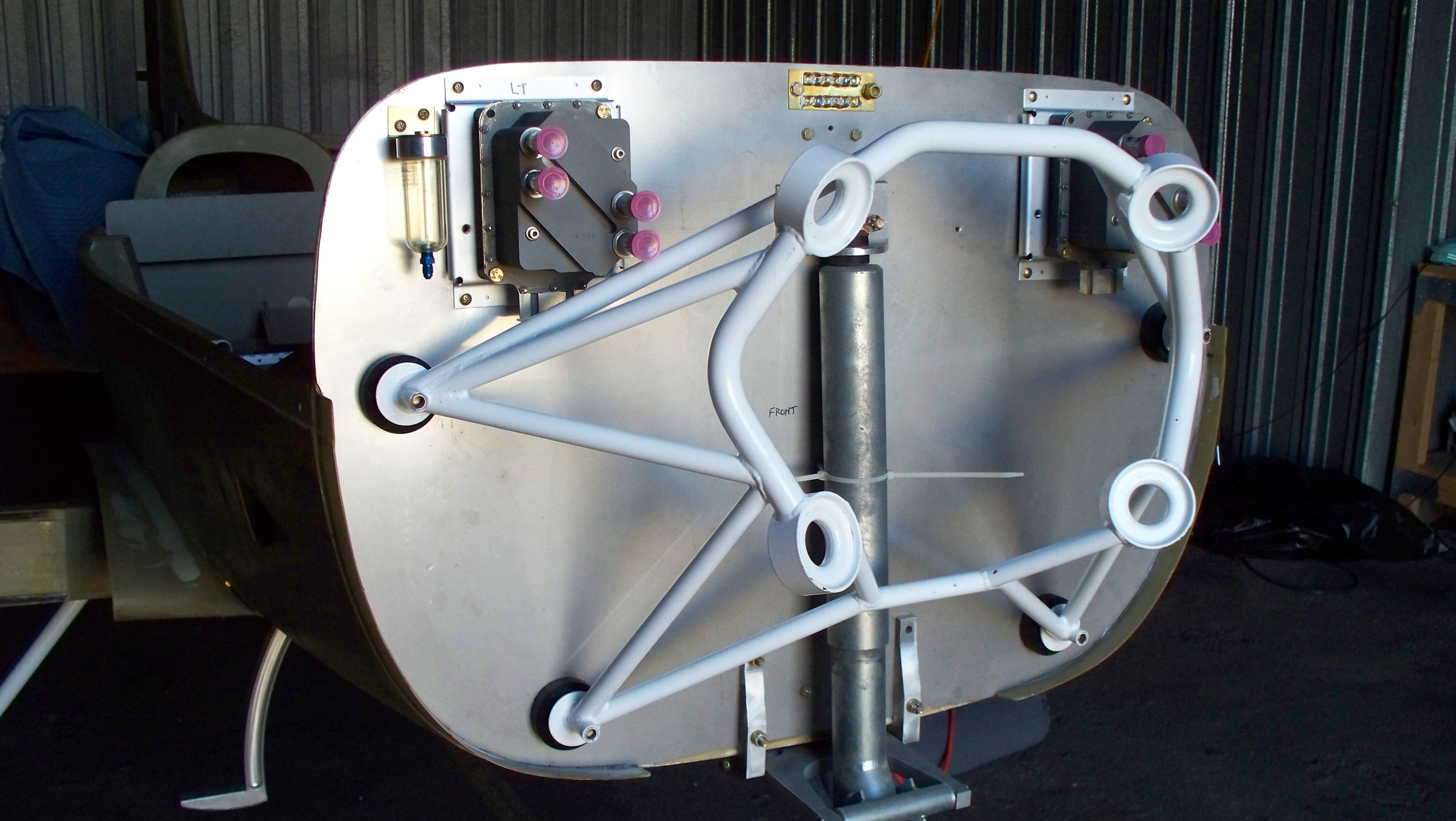 |
| Nothing really mounted yet but its already starting to look
like a lot of fun. The power ground and the brake fluid reservoir have been added in the most out of the way positions I could find. Drilling holes through that Stainless is sure fun and can destroy a drill bit in no time at all. |
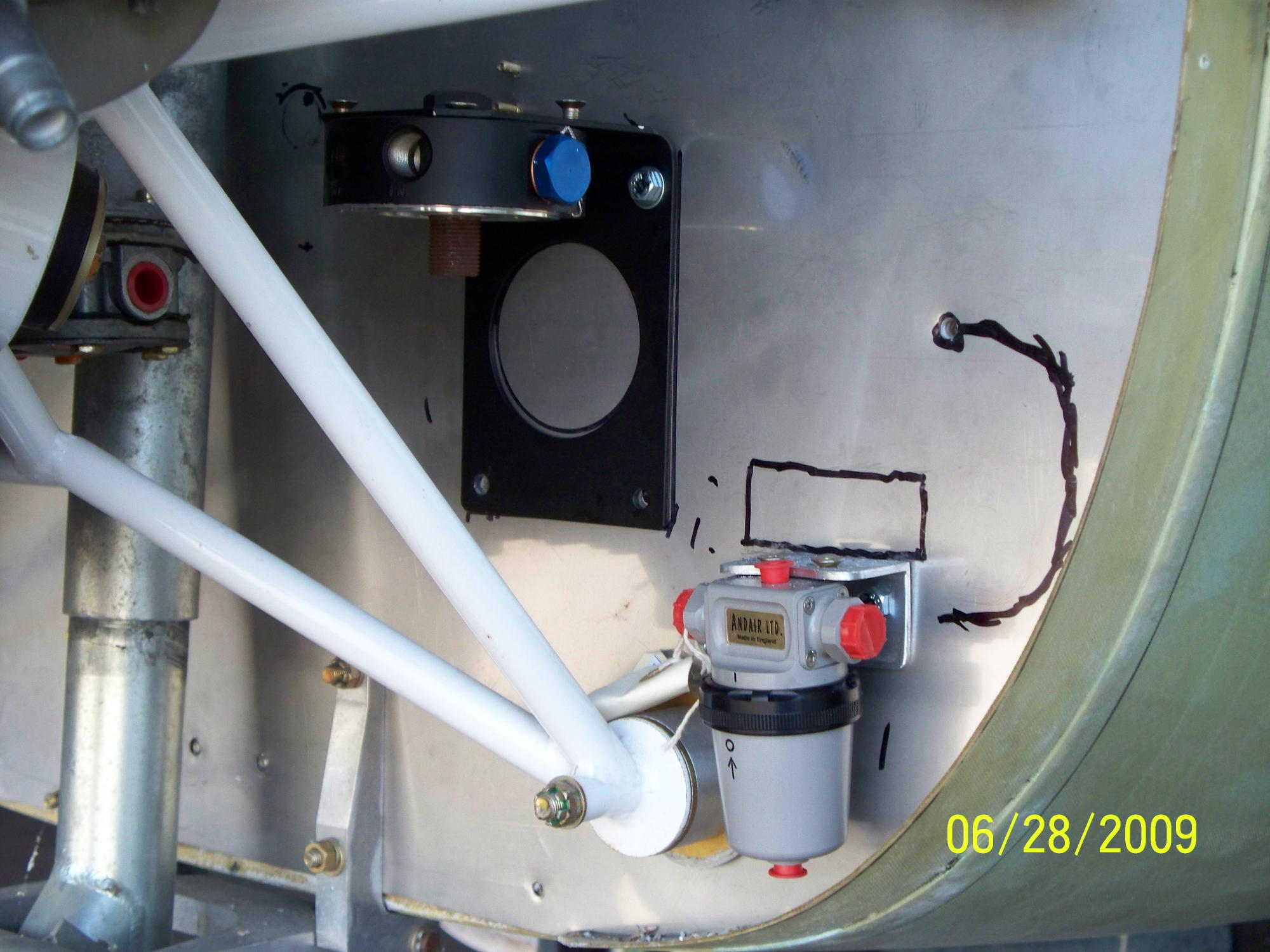 |
| Is it an art...or a science? Trying to locate
everything on the firewall to give both access and safety for routing controls, fuel lines and oil lines is more of a trial and error than art or science. I picked the lowest and closest point for the GasColator. The ugly black marks show the plan for routing the fuel line. This position will give me a fairly straight shot to the engine fuel pump shown in the upper left. A flexible hose will be used with a tie off to the engine mount. The remote oil filter is also in an easily accessed position just below the engine adaptor. |
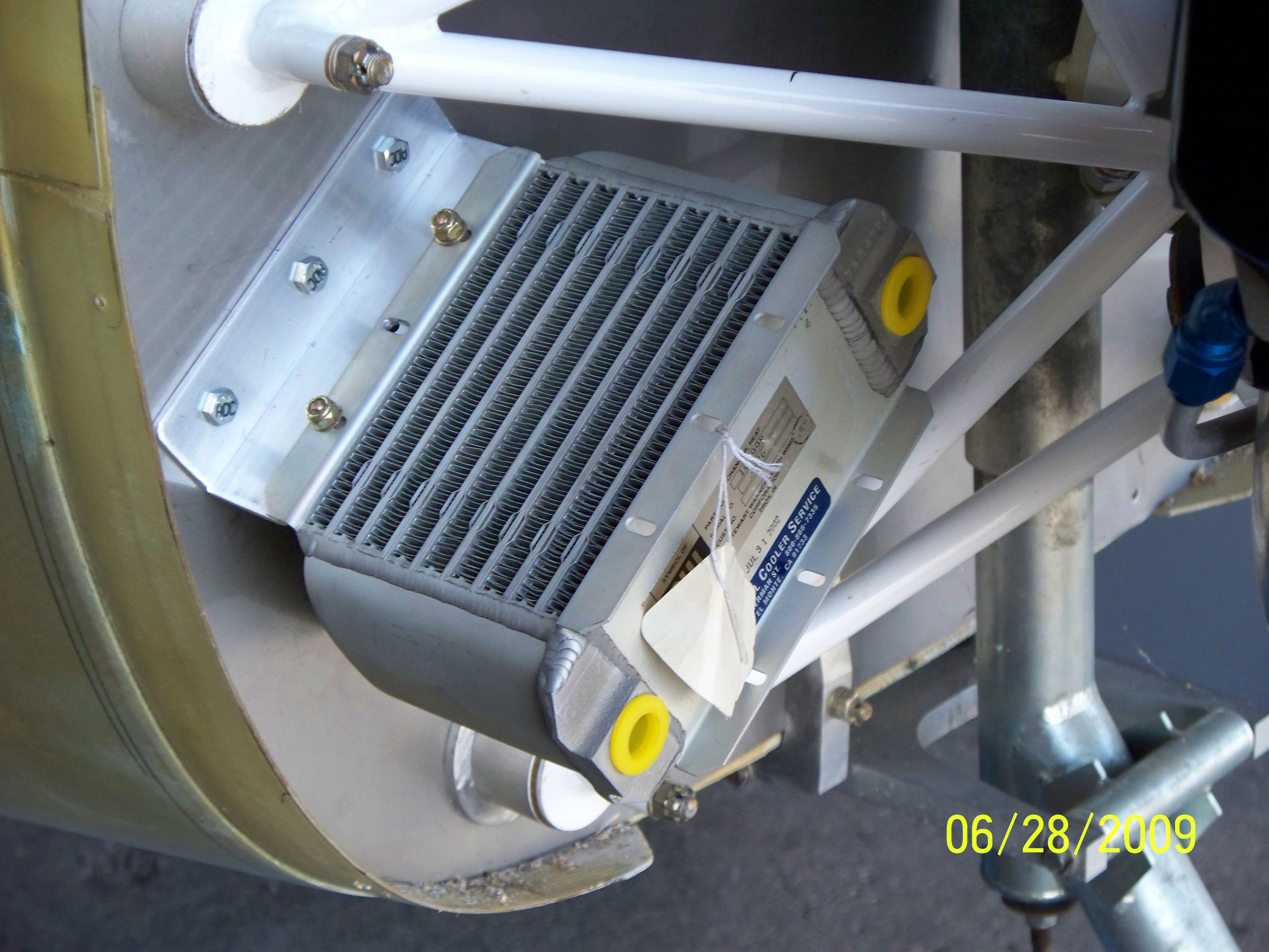 |
| Finding a good position for the oil cooler that would allow
for good routing of the scat tube supplying the cooling air was also a trial and error experiment. I hope this position will work out OK and be clear of all the exhaust pipes when the oil lines are installed. The plan is to use right angle fitting that will direct the oil lines directly upward. |
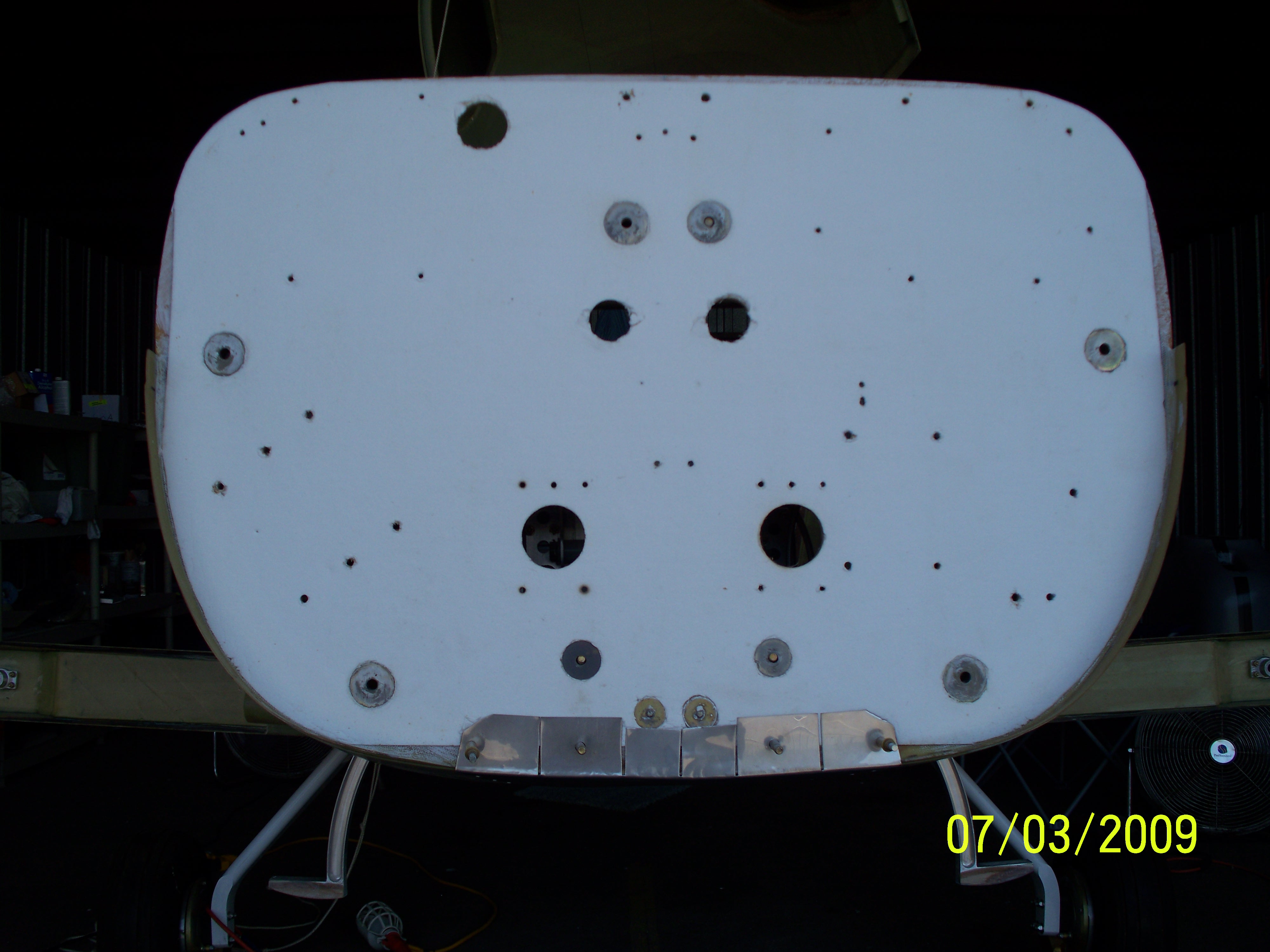 |
| The stainless steel firewall has been removed to show the
fiberfax facing. The main reason I included this was to show the forward mounting of the protective pan under the fuselage to protect it from the heat of the exhaust system. I still have about a dozen more holes to make in the firewall for control cables, battery cable, and electrical cables. |
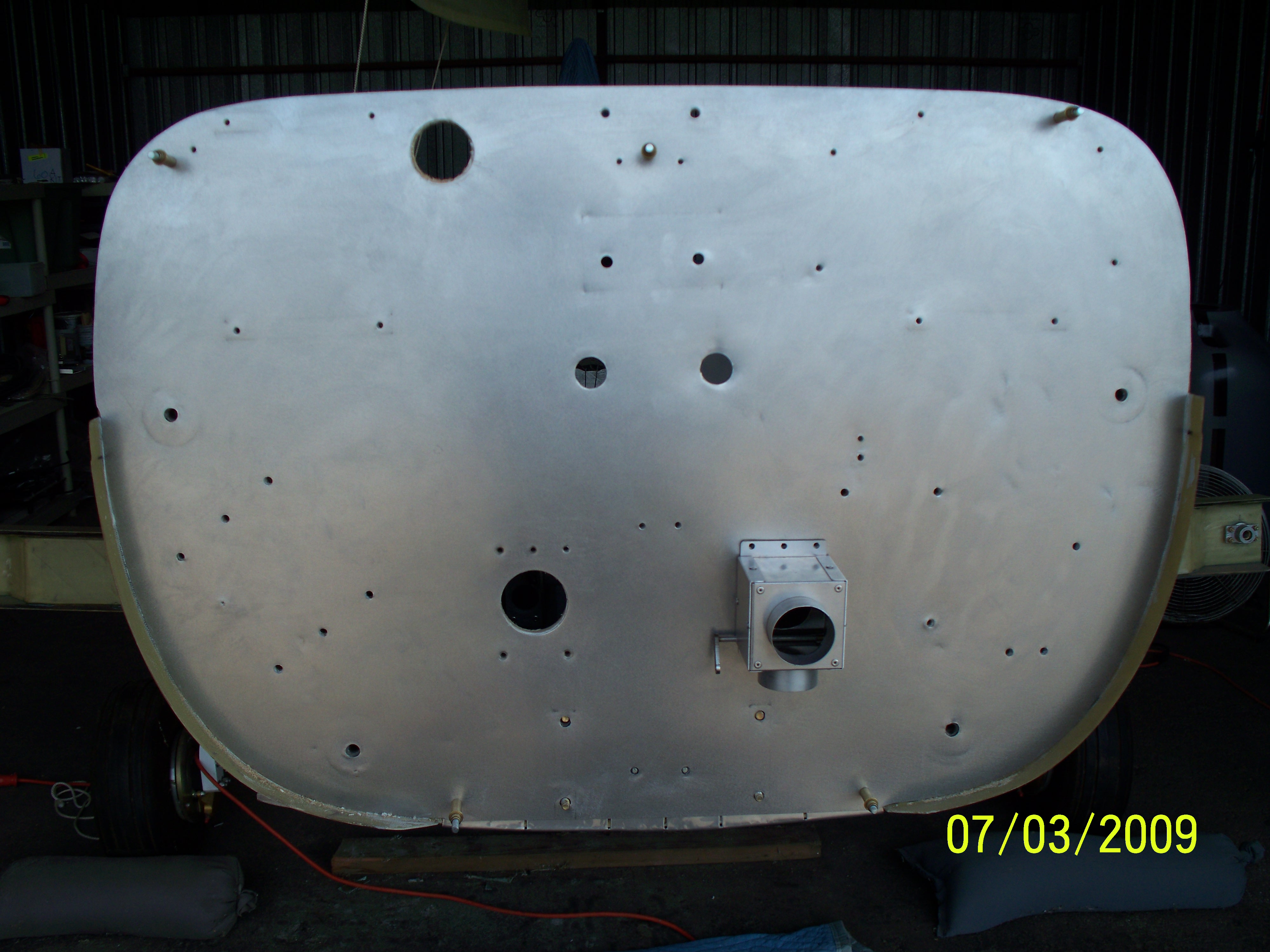 |
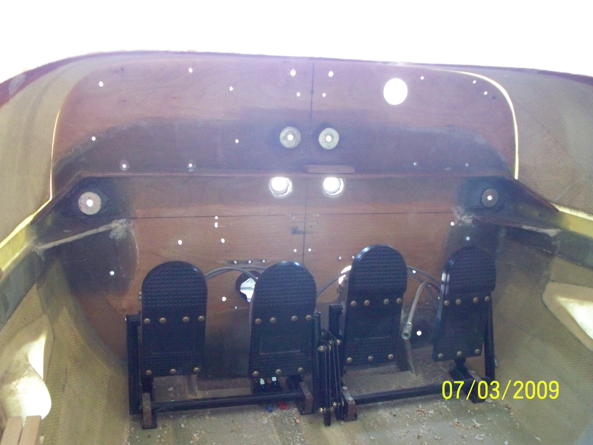
| Before putting the stainless steel firewall back in place I
used a random orbital sander to remove the shine from the surface. I like this surface treatment instead of the mirror surface that shows every scratch and finger print. One thing to note is the three large opening. The top opening is for a "T" fitting that will supply heat for the windscreen defroster. The other two openings will be used for the heater control boxes. (One shown in place.) The placement of these openings was picked to minimize the amount of scat tubing that would be required on both the inside and outside of the firewall. The heater shroud will be on the co-pilot side. The heater output will be split by a "Y" tube to the upper defroster input. The second tube will be split to the two heater controls using another "Y" tube. This gives the pilot and copilot separate heater inputs. The inputs are directly behind the rudder pedals and will have a hood to direct the heated air downward and under the rudder pedal platform. When the heater controls are closed the heat will be directed down toward the cowling air exit. |
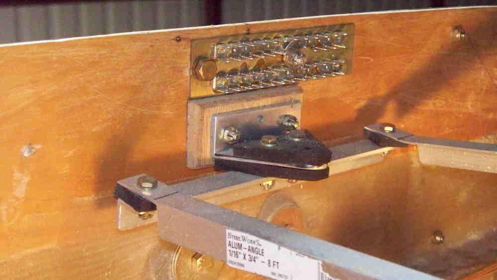 |
| The inside of the firewall is going to be equally crowded but
with slightly different issues. The inside will be very crowed with wiring and other fixtures. This shows the inside mounting of the common ground connection. The bracket shown in this photo is part of the support system for the instrument panel. The entire instrument panel will be shock mounted. The bracket shown connects at two points on the top of the instrument panel. |
 |
| And I still have another dozen holes to put into the firewall
before it is complete. It already looks like the target for machine gun practice and there is not a single hole that is not required. |